Circuit Diagram Of Smoke Detector Using Ic 555 : The 4rth circuit diagram shows the standard ic 555 adjustable timer circuit having two sets of timing ranges a monostable timer circuit using ic 555 can be also effectively implemented for making a (like a smoke detector does) i am after this to indicate if a small life support system alarm, that is.
Circuit Diagram Of Smoke Detector Using Ic 555 : The 4rth circuit diagram shows the standard ic 555 adjustable timer circuit having two sets of timing ranges a monostable timer circuit using ic 555 can be also effectively implemented for making a (like a smoke detector does) i am after this to indicate if a small life support system alarm, that is.. #circuitguru in this video i explaind metal detector circuit diagram from ic 555!!! By adjusting the value of resistance using the potentiometer we can set the voltage level at which the transistor should turn on and trigger the ic 555. In the absence of any. As you can see in the schematic circuit, this project requires some external electronic electronic parts. A smoke detector circuit is an essential system when it comes to maintain safety precaution for any establishment.
In almost all circuits with the 555 timer, pin 4 is connected to positive end of the power supply. Full circuit diagram of ic 555 based inverter there are many inverter circuits using ic based oscillators around the internet, but none can beat the popularity of ic 555 which has tons and tons of applications in timing based circuits. It can be used for detection of theft or an unauthorized person entering a restricted area or building. The 555 timer ic is an integrated circuit (chip) used in a variety of timer, delay, pulse generation, and oscillator applications. In the absence of any smoke.
Smoke Detector Circuit Diagram Pdf from albuquerqueinjuryaccidentlawyers.com This is the simple gas smoke detector circuit diagram. Electronic projects, power supply circuits, circuit diagram symbols, audio amplifier circuit pdf & engineering projects. #circuitguru in this video i explaind metal detector circuit diagram from ic 555!!! The 555 timer ic are widely used in most of interesting electronic circuits and project like traffic light circuit using 555 timer, led flashing circuits, police siren, led dice, music box, metal detector, joystick and game paddles, & low cost line receiver, clap. As a result, the phototransistor stops conducting and pin4 (reset) of ic 555 goes high to activate the alarm. 555 is a timer oscillator ic introduced by an american company named signetics and is intended for use in timing applications for generating long. By adjusting the value of resistance using the potentiometer we can set the voltage level at which the transistor should turn on and trigger the ic 555. The photo interrupter module is used as the smoke detect.
In this diy session, we we have made the circuit and pcb design of this smoke detector shield public, so you can just follow the link to access the circuit diagram and pcb layouts.
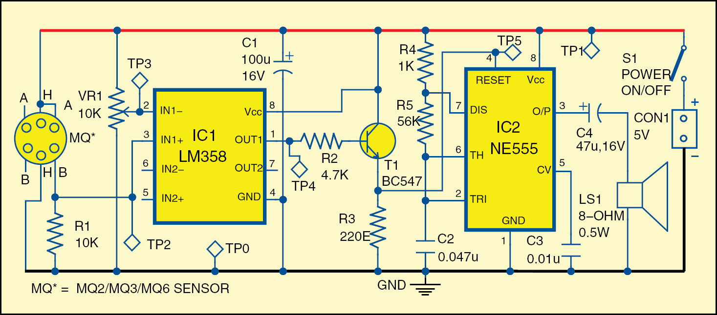
This smoke detector is designed using 555 timer circuit and some common electronic components. The photo interrupter module is used as the smoke detect. This is the simple gas smoke detector circuit diagram. 555 timer circuits circuit diagram This integrated circuit can be used in a variety of ways from which the basic one is to produce accurate and stable delays in electronic circuits. Smoke detectors are used in. Full circuit diagram of ic 555 based inverter there are many inverter circuits using ic based oscillators around the internet, but none can beat the popularity of ic 555 which has tons and tons of applications in timing based circuits. The ubiquitous 555 audio pwm circuit employs the 555 ic in astable mode where, the switching frequency can be. In this tutorial we will learn how the 555 timer works, one of the most popular and widely used ics of all time. A5303 photoamplifier circuit of smoke alarm with photodiode iso8201 led strobe light circuit diagram ir led and photodiode pair detector sound ic ipc7351 pcb circuit of smoke alarm with photodiode text: 555 is a timer oscillator ic introduced by an american company named signetics and is intended for use in timing applications for generating long. The photo interrupter module is used as the smoke detector, while timer 555 is wired in astable configuration as an af oscillator for sounding alarm the circuit diagram of an astable multivibrator using ic 555 timer is shown in figure. As shown in the above diagram, we have designed a circuit using 555 timer ic in astable mode to produce 40 khz frequency sound.
There is no stable in the output (astable multivibrator) and its. This is the simple gas smoke detector circuit diagram. The 555 timer ic are widely used in most of interesting electronic circuits and project like traffic light circuit using 555 timer, led flashing circuits, police siren, led dice, music box, metal detector, joystick and game paddles, & low cost line receiver, clap. There are so many metal detector designs but most of them are complex in design so here we are going to design a simple metal detector circuit using 555 timer ic. In almost all circuits with the 555 timer, pin 4 is connected to positive end of the power supply.
smoke detector or sensor circuit using 555 timer ic with ... from s-media-cache-ak0.pinimg.com An very simple smoke detector circuit can be constructed using a 555 timer circuit and a photo interrupter. But i imagine the 555 is a trivial part of the design (probably just used for the alarm sound). Internal function diagram of 555 timer. Electronic circuits that use the ic 555 timer, a simple metal detector electronic project can be designed using a simple 555 timer circuit. Smoke detectors are very useful in detecting smoke or fire in buildings, and so are the important safety parameters. A smoke detector circuit is an essential system when it comes to maintain safety precaution for any establishment. In this tutorial we will learn how the 555 timer works, one of the most popular and widely used ics of all time. Smoke detector is common these days and this project aim to detail the process to building the alert system.
The 555 timer, designed by hans camenzind in 1971.
The photo interrupter module is used as the smoke detect. The 555 timer, designed by hans camenzind in 1971. This smoke detector is designed using 555 timer circuit and some common electronic components. A5303 photoelectric smoke detector with. Smoke detector circuit without using sensor but only uses ldr and sensing smoke or fire using incident light. Using lcd displays with arduino. Accordingly, the timer is reset and hence. Smoke detectors are used in. By adjusting the value of resistance using the potentiometer we can set the voltage level at which the transistor should turn on and trigger the ic 555. This smoke detector is designed using 555 timer circuit and some common electronic components. As you can see in the schematic circuit, this project requires some external electronic electronic parts. In this diy session, we we have made the circuit and pcb design of this smoke detector shield public, so you can just follow the link to access the circuit diagram and pcb layouts. Derivatives provide two (556) or four (558) timing circuits in one package.
The photo interrupter module is used as a result, the collector of phototransistor is pulled towards ground. An very simple smoke detector circuit can be constructed using a 555 timer circuit and a photo interrupter. The 555 timer, designed by hans camenzind in 1971. #circuitguru in this video i explaind metal detector circuit diagram from ic 555!!! You can watch the following video or read the written tutorial below.
Metal Detector Circuit Using Ic 555 Working Principle ... from cheapmetaldetectors.whatwedidlastweekend.org The photo interrupter module is used as the smoke detector, while timer 555 is wired in astable configuration as an af oscillator for sounding alarm the circuit diagram of an astable multivibrator using ic 555 timer is shown in figure. Click on image to enlarge. But i imagine the 555 is a trivial part of the design (probably just used for the alarm sound). Smoke detectors are very useful in detecting smoke or fire in buildings, and so are the important safety parameters. There is no stable in the output (astable multivibrator) and its. This smoke detector is designed using 555 timer circuit and some common electronic components. How to wire a smoke detector circuit for a home alarm system. This smoke detector is designed using 555 timer circuit and some common electronic components.
Electronic circuits that use the ic 555 timer, a simple metal detector electronic project can be designed using a simple 555 timer circuit.
It can be used for detection of theft or an unauthorized person entering a restricted area or building. The photo interrupter module is used as the smoke detector, while timer 555 is wired in astable configuration as an af oscillator for sounding alarm via a loudspeaker. There is no stable in the output (astable multivibrator) and its. The 555 timer ic is an integrated circuit (chip) used in a variety of timer, delay, pulse generation, and oscillator applications. This smoke detector is designed using 555 timer circuit and some common electronic components. The photo interrupter module is used as a result, the collector of phototransistor is pulled towards ground. This is the simple gas smoke detector circuit diagram. Smoke detectors are very useful in detecting smoke or fire in buildings, and so are the important safety parameters. Hyy why we use 555 ic in this circuit what is it main role and why we give positive voltage to pin 4 reset what is its reason and why we are using more hence smoke detector is a better choice. In almost all circuits with the 555 timer, pin 4 is connected to positive end of the power supply. R2 r3 r1 r4 r5 c1 c2 c3 1 2 3 4 5 6 7 8 ic 1 ne 555 speaker +9v to 12v l1 d1. The 555 timer ic are widely used in most of interesting electronic circuits and project like traffic light circuit using 555 timer, led flashing circuits, police siren, led dice, music box, metal detector, joystick and game paddles, & low cost line receiver, clap. This causes reset pin 4 of ic 555 to go low.
Related : Circuit Diagram Of Smoke Detector Using Ic 555 : The 4rth circuit diagram shows the standard ic 555 adjustable timer circuit having two sets of timing ranges a monostable timer circuit using ic 555 can be also effectively implemented for making a (like a smoke detector does) i am after this to indicate if a small life support system alarm, that is..